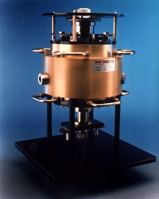
Thermal Technology’s fiber drawing furnace is designed for operation to 2400°C with preforms up to 100 mm in diameter. It features a simplified long-life, high-purity graphite resistance element which delivers concentrated heat through a linear graphite tube (available with a split liner for altering the hot zone profile) that serves to protect the element and control inert gas flow. Additionally, the encapsulated graphite felt insulation surrounds the heating element. Protective inert gas flow routing is simple and effective with top and bottom gas screens, top adjustable iris assembly and bottom water-cooled slide door assembly.
Safety interlocked top and bottom plugs permit convenient evacuation and backfilling of the furnace prior to operation. Our fiber drawing furnace includes a 30 kVA power supply, complete with a separately housed main transformer in a NEMA enclosure and 10′ feet’ (or longer) of flexible power cables to couple the furnace to the transformer.
Fiber Drawing Furnace Operating Gas
The fiber drawing furnace MUST be operated with an inert gas (helium, argon or an argon/helium mixture). Furthermore, the gas must be dry and oxygen-free: less than 1 PPM water and oxygen. We recommend using Thermal Technology’s Gas Purification System (Model IGP).
Recommended Accessories
- Vacuum Pump
- Gas Purification and Oxygen Analyzer
Entry and Exit Ports
You can close the top port with a single sliding water-cooled door when there is no preform in the furnace. In open position, the door provides an opening of 2.5” (63mm). And you can close the bottom port with dual sliding water-cooled doors with a minimum opening of 0.25” (6mm). Replaceable iris diaphragm assemblies are available as options for both the top and bottom ports. The irises have an adjustable range of 0.2” (5 mm) to 2.5” (63 mm).
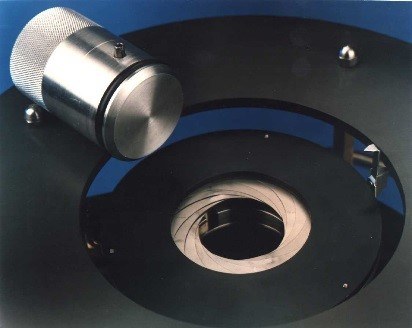
Entry port
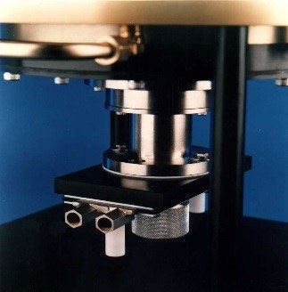
Exit port
Radial Ports
Two 1-⅛” 16 threaded ports are provided to view the center of the furnace hot zone. Both ports view the heating element through a 0.31” (8 mm) diameter sighting hole. One port is located 45° to the right of the front of the furnace, the other 90° to the left (135° apart).
We’ve installed a window in the left port which views through the element, while the right port views the exterior of the element for accurate temperature control using an optional radiation pyrometer. This port is plugged, but will accept the standard window assembly.
Gas Ports
Ports with compression fittings for ¼” (6 mm) outside diameter tubing are provided for gas inlets and venting. All fittings extend toward the rear of the furnace and serve the following purposes:
- Top gas curtain, inlet, with quick disconnect.
- Bottom gas curtain, inlet, with quick disconnect.
- Radial purge, inlet. This port admits inert gas into the thermal insulation area for purge prior to beginning furnace heat-up.
- Radial pressure monitor. This port allows connection of a very low pressure gauge (1 inch water) to monitor interior pressure with respect to the exterior.
Vents
Gas inlets at top and bottom gas curtains flow to the center of the draw hot zone, exit this area radially, and flow outside the liner tubes to exit at the bottom of the furnace. We also provided an additional vent port at the top to allow optional gas flow pattern from the bottom and exiting at the top.
Fiber Drawing Furnace Interior Access
You can complete all fiber drawing furnace maintenance without removing the fiber drawing furnace from the drawing tower, disconnecting any water-cooling lines or removing any radial windows or control instrumentation.
You can replace the bottom graphite liner by removing the fiber drawing furnace bottom door/gas screen assembly. Similarly, you can replace the top graphite liner by removing the top door/gas screen assembly. And you can replace the heating element by additionally removing a top cover plate. We secured the heating element at the top to power electrodes using two taper clamps having four mounting screws each. When you remove the top furnace head, you can then lift the entire thermal insulation assembly from the fiber drawing furnace as a one piece assembly. Power cables can remain connected for all operations described.
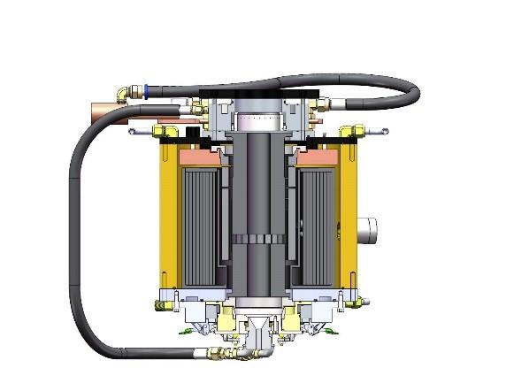
Fiber Drawing Furnace Interior Components
The fiber drawing furnace interior is free of ceramics and other possible contaminating materials. All components are solid, ultra-purified graphite having a typical ash content less than 20 ppm.
The fiber drawing furnace assembly is completely sealed with Viton O-rings. Optional end caps are available to allow vacuum purging prior to operation. These solid caps replace the top and bottom iris diaphragms for vacuum operation.
Power Supply
The furnace power supply and controls are enclosed in separate cabinets. A base mounting enclosure 24” wide x 28” deep x 45” high (610 mm x 730 mm x 1140 mm) contains the main power transformer and can be positioned on or near the drawing tower. Top exiting flexible power cables 10’ (3 m) long connect the furnace to the power transformer (longer cables optionally available). This enclosure also contains the following components:
- SCR (thyristor) power regulator
- Furnace power contactor
- Control power step-down transformer
- System fusing
- Water distribution manifold and flow switches
Facility sources of operation power and cooling water are connected into this enclosure.
We’ve enclosed the furnace controls in a separate bench mounting cabinet which is provided with standard 19” notched rack mounting extensions. Cabinet size is 17” wide x 14″ deep x 10.5” high (430 mm x 355 mm x 267 mm).
Fiber Drawing Furnace Control Cabinet:
- Control power on-off switch
- Furnace power on-off buttons
- Operate/reset switch
- Indicator lamps
- Water flow warning lamp and alarm
- Furnace power (transformer secondary) ammeter and voltmeter
- Automatic temperature controller
The power supply range provided allows beginning operation at the higher currents and having voltage reserve available for operating as the heating element ages and its resistance increases. This allows continuous operation without the requirements to shut the system down to change transformer voltage taps.
A safety interlock with warning lamp, audible alarm, and operate/reset switch monitors cooling water flow and will shut the system off in case of insufficient flow for furnace cooling.
The furnace connects the control cabinet and power supply enclosure with 16’ (5m) of cable.
Automatic Temperature Controller
Eurotherm (or equivalent) single channel, automatic temperature controller/ programmer. Mounted in the control console.
Temperature Sensor
A two-color optical pyrometer with optical head and mounting flange to mate with optical window. Temperature range TBD based on use and model.
Facility Requirements
Electric: The power supply is completely wired for operation from one source of single phase, 150 ampere power. Facility voltage required is 208/230 volts, 60 Hz or 220 volts, 50 Hz. We have other options for operation from 440/480 or 380 volts, single or 3 phase power at additional cost.
Water: The furnace requires cooling water at a minimum continuous rate of 4.0 gpm at 55 psid, 65-85°F (14 liters/minute at 380 kPa, 18-30°C). Filter the water if it contains sand or other solid matter.
Operating Gas: The furnace must be operated with an inert gas: nitrogen or argon/helium. Furthermore, the gas must be dry and oxygen-free, less than 1 ppm H2O and O2. We recommend using Thermal Technology’s Gas Purification System.